| David L O Smith - Home |
LMS Class 8F 2-8-0 |
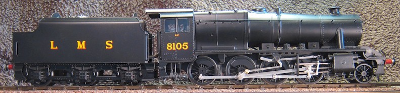
A 7mm scale (O Gauge) model of an 8F class freight locomotive No. 8105 built by the LMS at Crewe in January 1939 and withdrawn by British Railways in March 1967. I described in a Gauge 0 Guild Forum topic (Reworking a FineScaleBrass 8F) how I reworked this RTR model by FineScaleBrass, along the lines of the Rood Ashton Hall, but I have produced a lightly edited version of the exercise here.
I purchased this excellent model in 2007, when the price was not much more than half of that today (June, 2012). Although I ordered an unpainted model, a painted one was waiting for me at the show; this was without additional cost but, in some ways, the paint was an inconvenience to my plans to dismantle it and add details.
At the early prices, I was attracted to the FineScaleBrass range of models as an excellent and cost-effective starting point for creating a good model in far less time than it would take me to build the same from a good kit. The models are made of brass and stainless steel (there are no whitemetal components) and are well detailed in the body but, in my opinion, are rather let down by the lack of detail below the running plate and the relatively ‘primitive’ rendition of the motion. Small screws allow the locomotive and tender may be dismantled to some extent but I did not hesitate to apply a soldering iron if need be; this is where the paint could be quite inconvenient.
The Stanier 4000 Gallon Tender
I shall start at the rear of the tender and work around with before and after photos to provide a reasonable structure to the story but you may jump to the 8F loco.
Although I started off with a riveted 4000g tender, later I choose to model 8105 which, being Crewe-built, required a welded tender; the ever helpful Randolph Chang, of San Cheng Crafts, was happy to exchange the tank for me.
I have removed the steam heat pipe and made a vacuum pipe that looks something more like to me. I have also replaced the characteristic San Cheng drawhook that adorns all their products but which looks like no mainline prototype that I have seen; whilst I was at it, I replaced the upper shackle with the correct two separate links. Not clearly seen here, but I also sleeved the buffer shanks and opened out the stocks to bring the buffer shanks up to size.
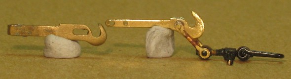
On the left is the original FineScaleBrass draw hook, which I find unacceptable, and to the right is the replacement with the two links in place of the inner shackle. I made these quite simply from little ‘doughnuts’ (drilled and parted-off, but could have been sliced from tube) that were silver-soldered to a short length of 0.8mm diameter wire; I reused the remainder of the original screw coupling.
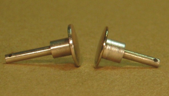
The buffers are retained by small cross-pins that are tack-soldered into holes in the end of the inner end of the shank; these pins may usually be removed by a swift tap from a hammer on a small pin-punch. Sometimes this in ineffective and the pins need to be filed off flush with the shank because there is just insufficient room to get in there with the soldering iron and the pliers. Once removed, the remnants of the pin may be extracted by unsoldering or be punched out. The buffer heads were the correct diameter, but they were not a great profile, and the shanks were decidedly on the thin side so I reprofiled the heads (running in the lathe) with a file and I pressed machined brass sleeves over the shanks to bring their diameter up from 3.9mm to 4.5mm. I tinned the sleeves with 145 solder and wiped them ‘dry’ with a tissue whilst the solder was still molten; I know nothing looks more like steel than steel but this works pretty well on a detail – and nothing rusts more like steel than steel, so I tend to avoid it in these situations (and stainless steel looks just like …. stainless steel, so I tin that too, but more about that later).
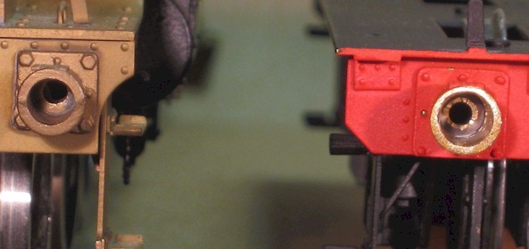
Having increased the diameter of the shanks, the stocks need opening up to suit. I opened them up from 4.0 to 4.6mm in 0.1mm steps (it pays to go very gently and slowly here, no tearing into the job). In the photo, the undrilled stock (on the left) is actually on a Black Five and the opened up stock (on the right) is on its tender.
Had I been working with a kit that had cast buffer stocks to be cleaned up and soldered on, I would have set them up in the lathe and bored them out a little at a time with a tiny boring bar, as I have done many times before. If the spigot is a bit poor or misshapen, I first turn up a mandrel to be a tightish fit on the hole I am going to bore out and I then press the casting onto it so that I may machine the spigot square and true. If the spigot at the rear is insufficient to get hold off for boring, I make a solder-chuck: a simple a piece of brass bar with a hole in the same size as the spigot that I can solder the spigot into (whilst the bar is still in the lathe chuck but out of the lathe, so all runs true for boring). However, in this case, given that the buffer stocks were already soldered in place, I simply gripped a 4.1mm drill in a drill chuck and proceeded to remove the material by hand, moving up to a 4.2mm drill and so on until I had opened them out to 4.6mm. That said, had I got into difficulty, I would have resorted to removing the buffer shanks but I have got away with it before.
I once did need to remove some buffer stocks from a part-built model (LNWR Cauliflower) that I acquired and, faced with the danger of unsoldering the buffer plank or doing other damage, I made a bespoke bit for my 40W soldering iron. I turned down the end of a piece of ¼” diameter copper bar (about 1½” long) so that it was a nice fit in the buffer stocks and went the whole way in. Once in the soldering iron and heated up, I placed it in a buffer stock and waited – not very long, as it turned out – until the stock came away on the bit and the buffer plank was relieved of any more heating. ‘Neat one’ I thought, rather satisfied with myself.
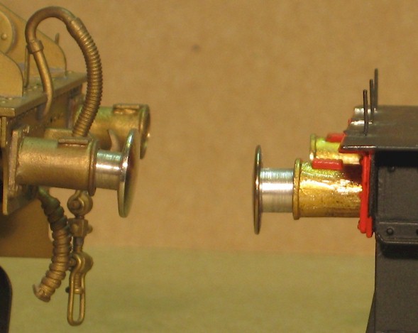
I feel that the result is worth the effort (but I concede that I am mildly mad when it come to these things) because, not only does the improved shank (on the right) show the chunkiness of the prototype, it supports the buffer rather better and prevents excessive droop (on the left). The buffer stock on the tender (on the right of the picture) is bright brass because I have removed the paint applied by FineScaleBrass as it had not adhered well because of the loose scale on the casting (I have also found this before).
Moving round now to the front of the tender:
Apologies for the drunken angle RHS
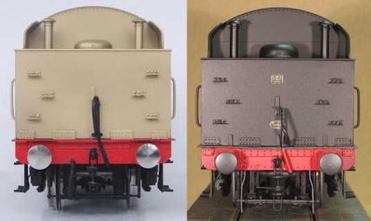
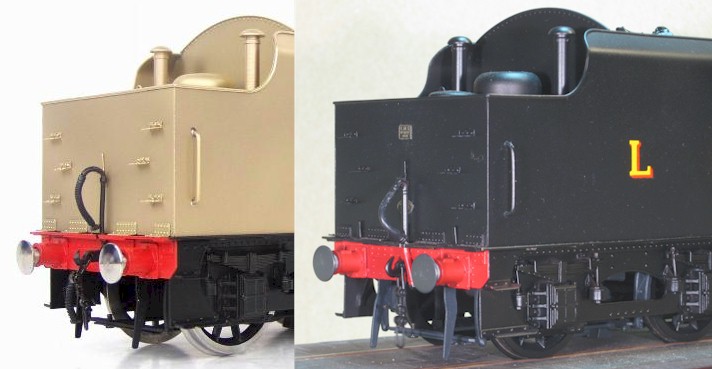
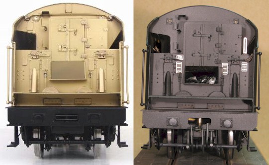
From the original tender (left) I have removed the BR era conduit and its support, and I have removed all the blank ‘cast’ plates and replaced the relevant ones with a set from Guildplates (right). I made up the handle ends of some fire irons and placed them in the tunnel (visible as brown ‘smudges’ on the upper left), a piece of fine chain to retain the water-scoop handle, and a water level indicator (shining on upper right). The latter was a simple milling exercise in brass and, as I have three other similar tenders to 'attack', I made four of them whilst I had the miller set up and all the settings noted. The tender is coaled and the next lumps for the firebox are visible on the shovelling plate. Between the tender-loco buffers may be seen the opened out dragbox housing the shortened free draw bar that semi-permanently couples loco and tender by a more prototypical distance than provided by the original peg and link arrangement.
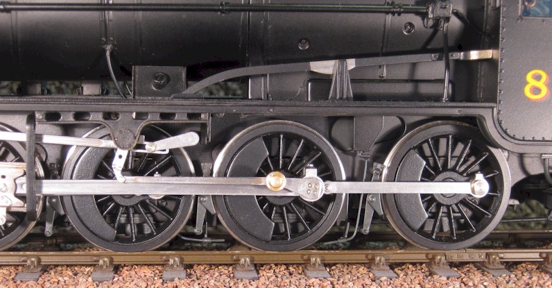
Now, it is sometimes surprising what a photograph reveals when you look at it – that the tender is off the road, in this case! (as you may have noticed in the first photograph at the top of this page, from which this image is cropped). Nevertheless it serves to illustrate that, like all the models from this manufacturer, the axles are sprung. However, the springs are so stiff that the models effectively run as rigid frames, unless you put a huge amount of weight in them; in fact, if you were to put sufficient weight in these tenders to deflect the springs by more than about 0.25mm, you would find that the flanges of the leading wheels rub on the bottom of the tank and those of the trailing wheels rub on the frames, as I discovered when I put in softer springs. A few minutes work with a fine file created relief notches.
Once the over-stiff springs were replaced with softer ones, another problem became apparent: these model tenders have ball bearings on all axles that are retained in brass hornblocks that slide in the (non-prototypical) inner frames – except that they don’t slide very well at all without the very stiff springs because they turn slightly in the hornguides and jam quite comprehensively. As I explain below, I cured this by milling the inner edges of the turned slots and soldering in some 10 thou thick nickel silver packing so that the edges of the slots were flat and parallel, which kept the hornblocks from rotating.
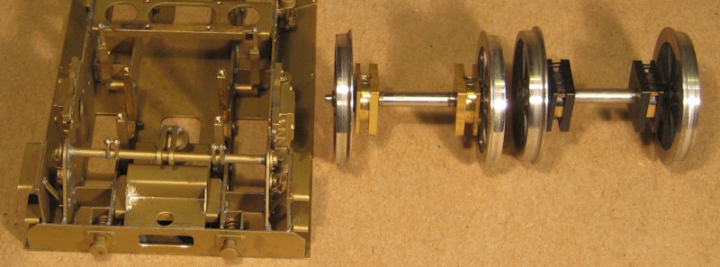
To the left of the picture above is an upturned set of tender frames, with the wheelsets, brake pullrods and water scoop removed; the brass horn guides (four posts screwed to the inside frames with tapped holes in their upper ends) may be seen between the axleboxes on the outer frames. I believe that the wheelset in the centre of the picture is fitted with the original design of hornblock – a simple turning of square stock material – that turns in the guides and jams. To the right of the picture is, what I believe to be, a later design that includes two pins in the upper corners to prevent the guides from jamming, which they don’t really. As you can see, the turned groove (and the pins) have also been milled to ease them into the guides. The examples here are both quite tidy but I have others (see below) that have also been fettled by hand with a file to ease the fit – none to precisely, to be honest. All this may be improved upon, however.
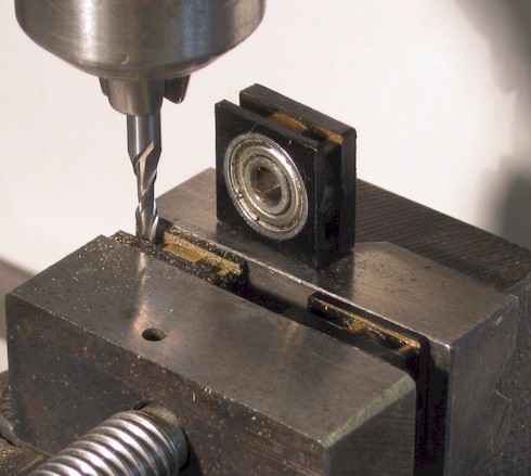
Sitting on top of the rear jaw of the machine vice just for the photograph, is a hornblock with its pressed-in ball bearing. This hornblock, and the one on the right in the vice, have seen attention from a file so the grooves are not as neat as the ones still on their wheelsets, shown above. The hornblock on the left in the vice has been deepened with a 2.0mm slotdrill, ready to have a piece of nickel silver strip soldered in (using a resistance soldering unit [RSU], a pre-tinned strip, a hint of flux and a wash out with soapy water from a syringe needle immediately afterwards).
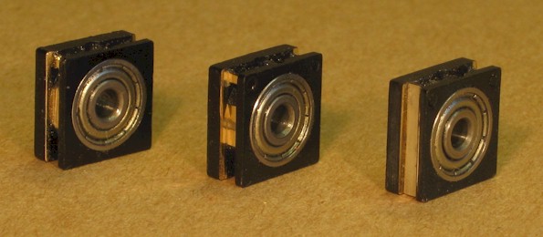
On the left, is a hornblock just as it came off and axle and it is clear that the slot/groove has been fettled a little heavy-handedly with a file. In the centre, is an example where the slot has been carefully milled down, as described above, to the bearing housing; the outer race of the bearing is just visible. On the right, is the finished item with a suitable strip of nickel silver soldered in the bottom of the slot.
To undertake the above modification, I had to remove the wheels to release the hornblocks so I could put them in the milling vice; when I replaced the wheels I included some turned spacers to remove almost all the leading and rear axle end-play and most of that on the centre axle. I return to this topic when I deal with the loco.
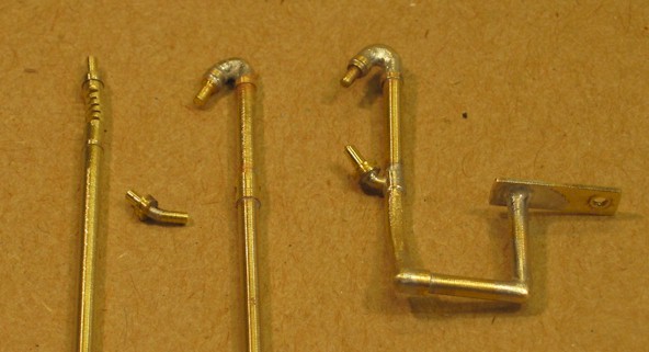
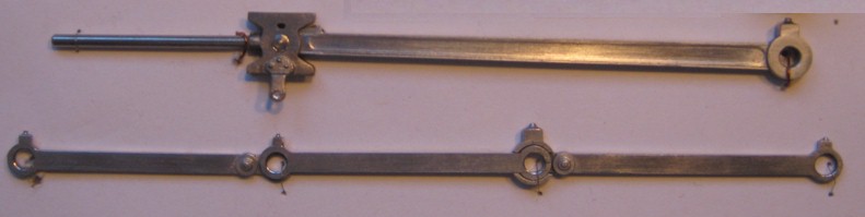
I made better looking vacuum pipe for the tender. On the left, I have ‘gashed’ a piece of 1/16” diameter brass rod, by sawing five slots about 2/3 of the way through and then opening them out with a triangular (three-square) file; I then slipped over two little collars (above and below) that I machined from 2mm diameter brass rod. As shown in the middle of the picture, these collars will represent the small flanges of the elbow that is made by bending at the gashed section and filling the gaps with solder (none too pretty in this cruel enlargement but they will clean up and will be fine when painted); a sleeve slipped on lower down the pipe is drilled to take the fixed plug that holds and seals off the ‘bag’ when not coupled to the next vehicle. A gentle bend follows and then another sleeve lower down again, when gashed with a square file about 2/3 of the way through, bent and soldered, forms the next 90 degree elbow; a simple gashed bend without a sleeve (too far under to be seen, but I suppose I could have used another sleeve here) turns the pipe upwards to a small plate that is screwed (12BA) to the underside of the tender frame to hold the whole assemble in place once painting is complete. The ‘bag’ (vacuum hose) will be cut from a length of marvellous black rubber tube that I picked up at Telford last year, which is ‘just made for the job’: it is the right size and it is much more flexible than the wire insulation that I used to have to drill out to make it behave.
Moving on to the loco, starting at the front end and considering the ‘before’ and ‘after’:
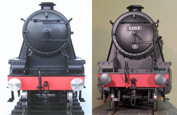
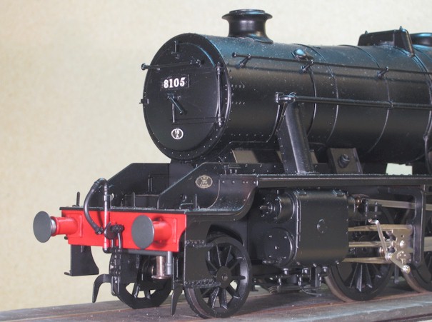
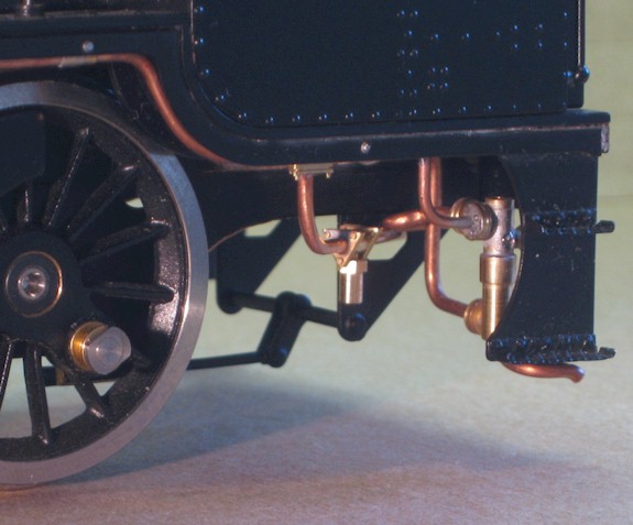
As I described earlier for the tender, I reworked the buffers, replaced the draw hook and upper shackle, and I made a new upstand for the vacuum pipe, continuing it along under the buffer plank to include the moisture trap below and behind the left hand buffer (on the right, as we view it here). Plates are from a set provided by Guilplates.
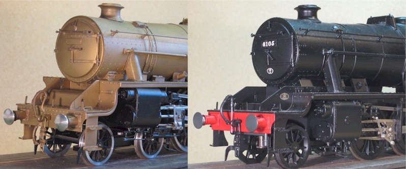
The ‘before’ photograph on the left is provided courtesy of my Black Five that is following the 8F through the works; for this exercise, as they are sufficiently similar not to detract from the point.
Moving round to the RHS, I replaced the brass cylinder drain pipes with nickel silver and added a strap to tie the three together; the original pipes on the model were already bent and one had come adrift from its mates. I added the central nut/bolt within a recess that I made in the cylinder cover and I turned the cylinder pressure relief valves through 90 degrees (to be side to side rather than up and down) and relocated them to the bottom centre, rather than slightly outboard where they were originally.
I opened up the hole in the running plate so that there was more to see between the frames and, because it is now rather obvious, I reduced the sizable cylindrical frame-spacer to a smaller rectangular section. The sandbox filler shields did not have turned up edges so I soldered some on (another job that would have been easier with an unpainted model) and the lubricators were fine but, being identical castings, their handles were both in the same position so I altered one with a new handle.
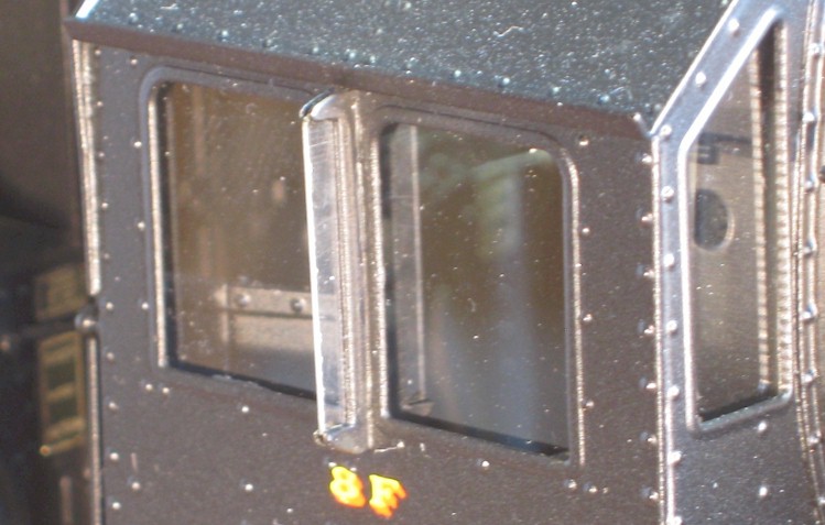
I fitted glass (microscope slide cover slip) to the cab windows and I replaced the little handrail with hand rail knobs (somebody misread the drawing?) between the side windows with a draught shield that I made in nickel silver; I milled out the profile and used a slitting saw to cut a slot for the clear styrene ‘glass’.
Moving around to the LHS of the loco, the main modification that I made was to the replace the reversing/reach rod with the more curved type for my prototype and to add the fork at the cab end.
The interior of the cab is very well detailed on these models but the ‘backhead’ is very hard to reach; fortunately, I have found them very easy to remove.
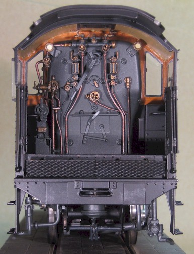
I do not know if, like the miners of old who had to buy their own candles, the assembly workers in China have to buy their own solder but they are certainly very sparing in its use. This is a potential problem and I have had to do a little ‘belt and braces’ resoldering on my models but I still had a cabside irritatingly ‘let go’ on my GWR Hall. However, in this instance the paucity of solder worked in my favour as I was able to ‘bother’ the tack-soldered joints with a small chisel (broken bicycle spoke flattened at the broken end and sharpened with the nipple retained on the other end to protect my hand) to free the backhead assembly to work on; it is now retained with a couple of pegs and a 12BA screw.
Similarly, I made the reverser assembly removable for the addition of a more detailed the screw reverser mechanism, including the notching up plate (the screw reverser mechanism is represented by a plain cylinder in the model) and for ease of painting.
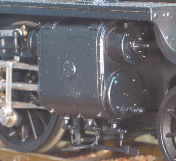
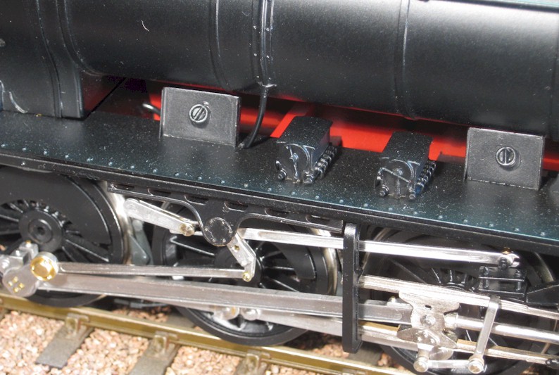
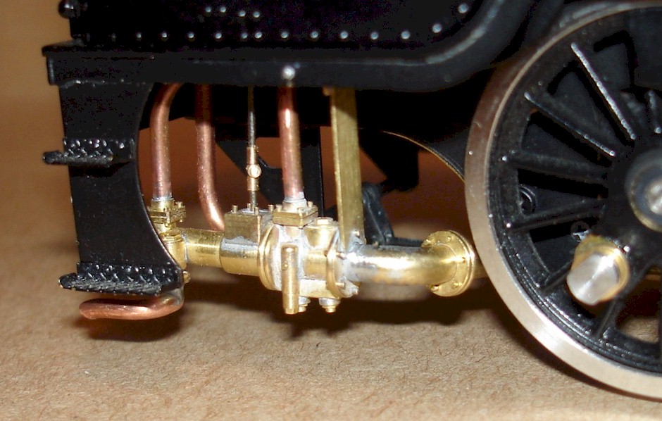
I removed the springs from the fall-plates that made them stick out horizontally, no matter what; I cannot see the point of these springs as the fall-plates could have been made rigid to achieve the same effect but fortunately they were free and now, because I have considerable reduced the loco to tender gap, the fall-plates rest prototypically on the tender footplate. Whilst at the rear end of the loco, and looking below the footplate, I made the vacuum cylinder and crank that operates the brake cross-shaft, the exhaust steam injector on the fireman’s side (right) and the live steam injector on the driver’s side (left), but I describe making these below.
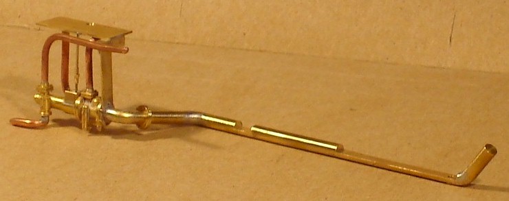
As I have commented above, these excellent models are rather let down by the detail (or rather the lack of detail) below the running plate and, as one of the last tasks I thought I would make up a Davies & Metcalfe exhaust steam injector (well, actually, I knocked out three because I also have a Black Five and Jubilee to deal with) to sit under the fireman’s side of the cab, although I could have bought a superior casting from Laurie Griffin.
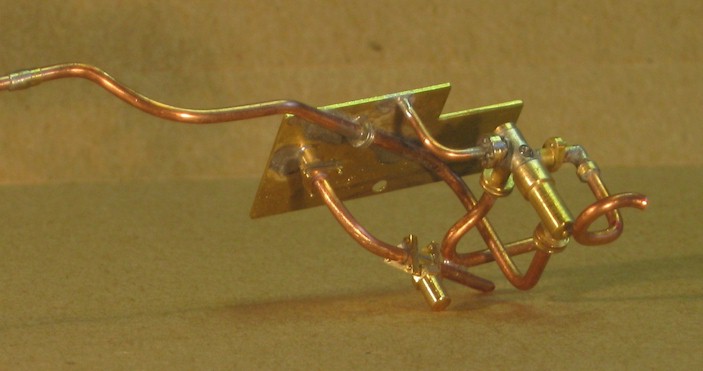
Now, ‘Once a detailed scratch builder, always a detailed scratch builder’ it seems to me as I appear to be quite incapable of just ‘knocking out something that will do’. I don’t know how long it took because I was distracted by other tasks but it wasn’t quick! There again, I found it thoroughly enjoyable and satisfying, which is really what it is all about. The complete assembly, including exhaust steam pipe is shown below. It is largely pinned and press-fitted together, and the solder is there to make sure it stays that way and to provide fillets on the fabricated ‘casting’.
A trial fitting showed that all is well:
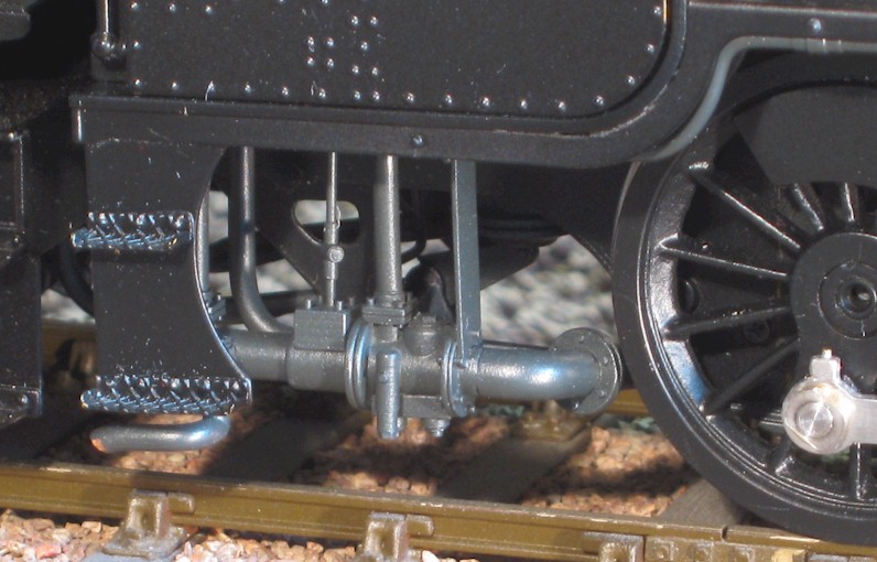
and a similar view on the completed model, where the ‘clutter’ of tender-to-loco pipes may also be seen:
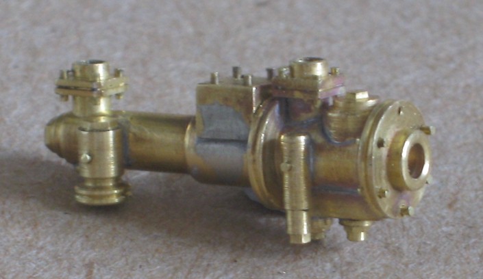
I made the live steam injector and the moisture trap in the train vacuum pipe under the driver’s side of the cab.
Again, a trail fitting to check that all was well and a similar view on the completed model, where the brake cylinder and crank may also be seen:
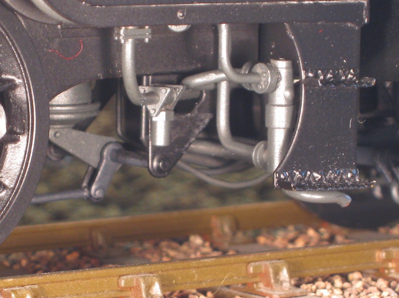
Looking underneath the locomotive:
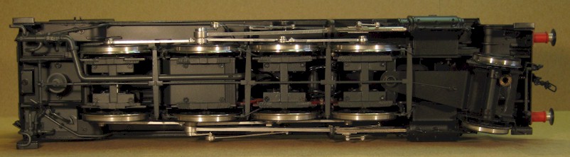
A somewhat undignified view from underneath best illustrates some of the additions that are not so easily seen in other views. Starting underneath the cab, there are the two injectors, the vacuum pipe moisture trap and the brake cylinder; the large exhaust steam pipe is seen running slightly off the centre line before turning to reach the exhaust steam injector (top left).
I modified ten whitemetal spring castings (the only whitemetal on the model) and soldered eight of them to stretchers that were in turn soldered to the keeper plates. The pair on the pony truck were soldered to a more realistic side frame that I made but they will appear more clearly in a photograph below. Clearly, the side control spring is a little weak and, once the loco has completed its running-in turns this summer, I shall replace it with something stiffer.
The vacuum pipe and another moisture trap may be seen under the front buffer plank (bottom right).
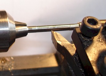
The stainless steel axle on the pony truck is quite prominent and needed painting but, to be able to pass it through the plain bearings afterwards without damaging the paint, I first turned down the centre portion by ‘a few thou’.
Turning now to the motion, which is where the greatest visual improvement may be made and in which there has been much interest. To me there is no doubt the design and manufacturing of these models is very well thought out and I recognise that compromises have to be made for production but I do think that the compromises made in the motion are out of step with those made on the rest of the model.
The coupling and connecting rods are cut from a single thickness of stainless steel and the motion parts are similarly cut from thinner material; flutes are stamped into the coupling rods and motion links, as appropriate.
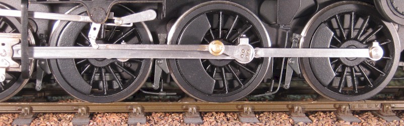
I decided that I would just have to accept the fluting as improving it (deepening and correcting the profile) would be a lot of work for probably little visual effect. On the other hand, I decided that I could make better looking dummy ‘knuckle joints’ on the coupling rods and that I could greatly improve upon the lack of decent sized bosses on the bigends and on the coupling rods at the crankpins. I made the bosses by turning a piece of nickel silver to diameter, milling a flat on one side and then silver soldering on a suitably sized rectangular strip to represent the oil boxes. I then cut off the embryo bosses with a slitting saw.
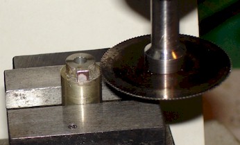
The last boss about to be cut from the prepared stock material.
The bigend was cut off each connecting rod and a spigot turned on its end that was a reasonable press fit in a hole drilled in the circumference of the boss (at 90 degrees to the oil box) so that the assembly could be silver soldered together.
Conrods before (right) and after (left) reworking.
I have only a poor quality photograph, so here is a close-up of the bigends (before and after) from a FineScaleBrass GWR hall that received the same treatment earlier.
The conrods were noticeably on the skinny side and so I added a strip of 0.25mm thick nickel silver top and bottom, which also improved the profile. Now, it may occur to you that we have a mixture of materials here and that none of them looks likes steel but tinning the silver soldered assembly all over and wiping it whilst still molten (as described for the shanks of the tender buffers, above) produces a very uniform surface that passes reasonably for steel; the nickel strips are similarly tinned all over and added using the RSU. Oil corks from brass wire complete the job.
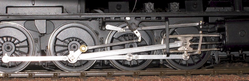
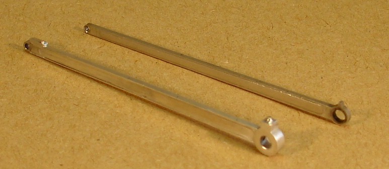
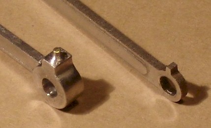
Connecting and coupling rods LHS
In replacing the connecting rod in the crosshead, I put a hexagon on the head of the gudgeon pin to represent the retaining nut. The chunky boss for the coupling rods required a little more machining to let in the smaller original boss of the centre rod and to accommodate the joint; when all is assembled, the joint is hidden and the dummy knuckle joints look as if they might be doing their job. I added larger oil boxes to the remaining bosses although I chose not to make them any thicker; I rather wish that I had now so I shall do when I come to the Black Five and Jubilee.
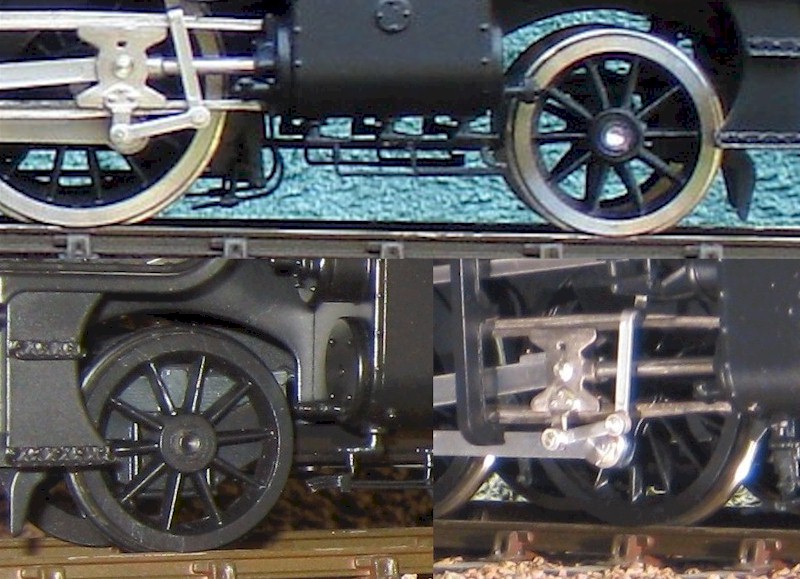
The valve gear before (left, courtesy Black Five) and after; the valve gears use
many common components.
In the same way that I try to use as many of the components supplied in a kit as I reasonably can, I have similarly tried to reuse components on this RTR locomotive. Thus, I reworked the ends of the radius rod (aka the valve rod) so that I could lower it in the expansion link to move the loco out of mid-gear; this allows the radius rod to reciprocate a little, which is rather pleasing. However, I had to make longer lift arms and expansion links (a fiddly job) that looked more like those of the prototype. In the same way, although I was able to reuse the long crankpin on the driven axle, I made a return crank of greater throw that looked more prototypical that I could solder on to it. I machined shallow flats on the ends of the other crankpins so that they could be tightened with a 10BA spanner but still looked plausible.
As supplied, the eccentric rod bigend is also rather skinny but I had chosen to model a locomotive that was built at Crewe, which required an even larger bigend to accommodate the ball bearing, and a brass cover.
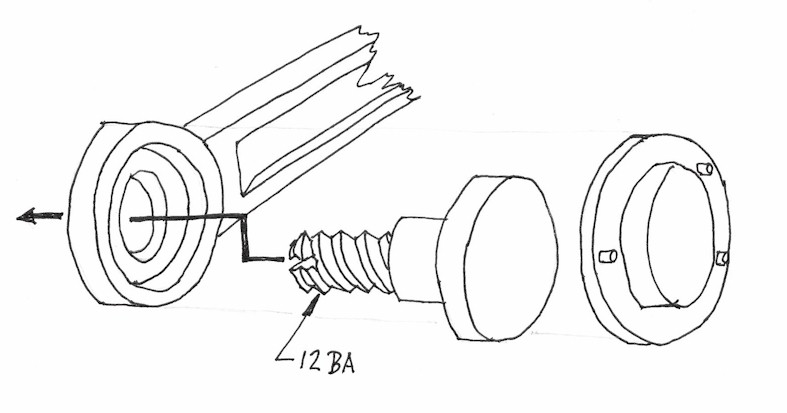
I made the enlarged bosses of the eccentric rod bigends and fitted them in the same way as for the connecting and coupling rods. The pin that retains the eccentric rod on the return crank is a sort of plain headed, shouldered screw with a slot in the ‘wrong’ end. To assemble it, the pin/screw is passed through the enlarged boss and a bespoke washer (not shown in the Ikea-type sketch above), the brass cover is soldered on and the whole assembly given a thorough wash, soak and rinse to remove the flux. Then, by passing a jeweller’s screwdriver through the 12BA tapped hole in the return crank, the pin is ‘unscrewed’ into place. I must say I was quite pleased with that.
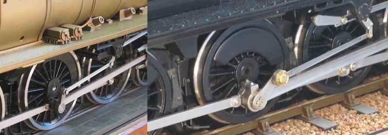
This composite is a rather cruel enlargement of three indifferent photographs but it does show before (above) and after (below) I added a more substantial frame and a dummy spring to the pony truck, and the improvement of adding bosses to the ends of the union link.
Some other modifications that I did not mention, because I did not have a suitable accompanying photograph:
i) Sides and front added to represent the lower firebox, the former may be seen through the rear cut-outs in the side frames and the latter may be seen between the frames; both were quite noticeably absent to me.
ii) The characteristic ring made and pressed on to the end of the Stanier hooter, which I had unsoldered to make a more realistic mount that could be reattached after the painting the body.
iii) Similarly, safety valves unsoldered, cleaned up and tapped 12BA to be reattached later
iv) I mentioned that I inserted spacers behind the tender wheels to take up nearly all the end-float, which required the wheels to be removed from their axles. Although removal and replacement is easy enough for tender wheels, I wished to avoid removing and replacing the driving wheels as I had on the GWR Hall. Successful though it was, I was concerned about re-establishing and then maintaining the quartering with the press fit of the plastic hub on steel axle. I experimented with C-shaped brass spacers (made by milling a slot in the circumference of a conventional, annular spacer) that I squeezed/sprung into place with fine-nosed pliers. This was highly successful and I shall use this simple technique in future.