| David L O Smith - Home |
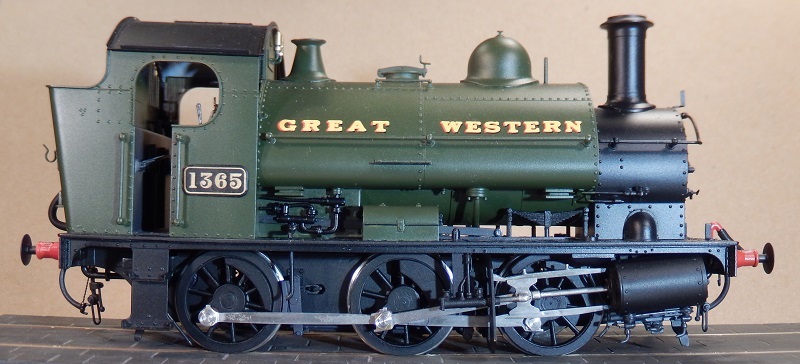
Great Western Railway 1361 Class |
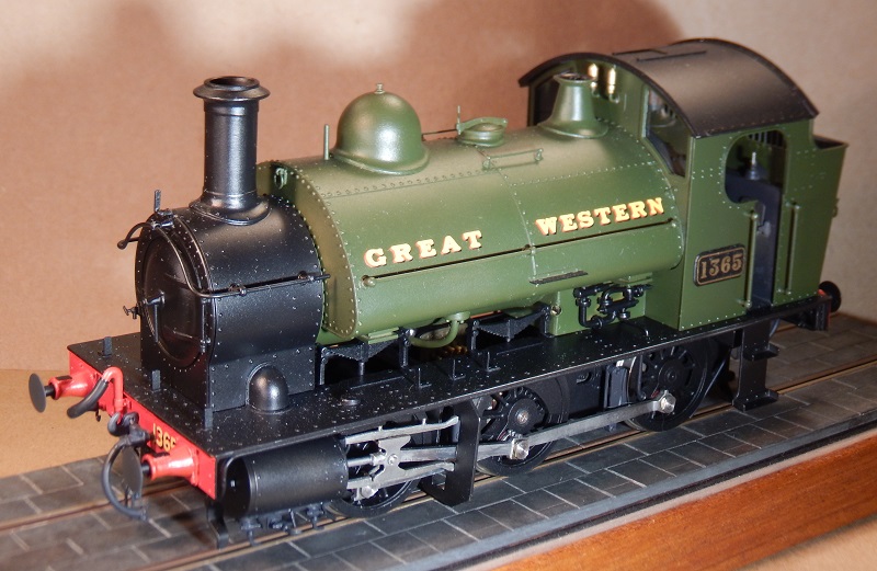
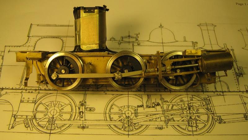
A 7mm scale (O Gauge) model of a 1361 class 0-6-0ST locomotive that was designed by George Jackson Churchward and built by the Great Western Railway at Swindon in 1910 and withdrawn by British Railways in 1961/2.
I bought the 'Tower Brass' model as a non-runner from Randolph Chang when he closed down his San Cheng Crafts factory in 2013 and I describe here how I rebuilt it along the lines of other models from this factory.
| Smokeboxdoor | Wheel balance weights | Cylinders and Drain cocks |
| Motion brackets | Motor, gearbox and frames | Brakes |
| Whistle and steam pipe flanges | Drawgear, vacuum and steam heat pipes |
Like so many of the models from this stable, particularly the earlier ones, the upper works are well engineered and are quite well detailed compared to the lower works, which rather let the models down, but they do all run very well. On this model, I have undertaken my usual reworkings of the motion, draw gear, vacuum and steam heat pipes and so on but the frames required quite drastic surgery to set them at more nearly the correct distance apart and to spring the driven centre axle, which was rigid in the frames.
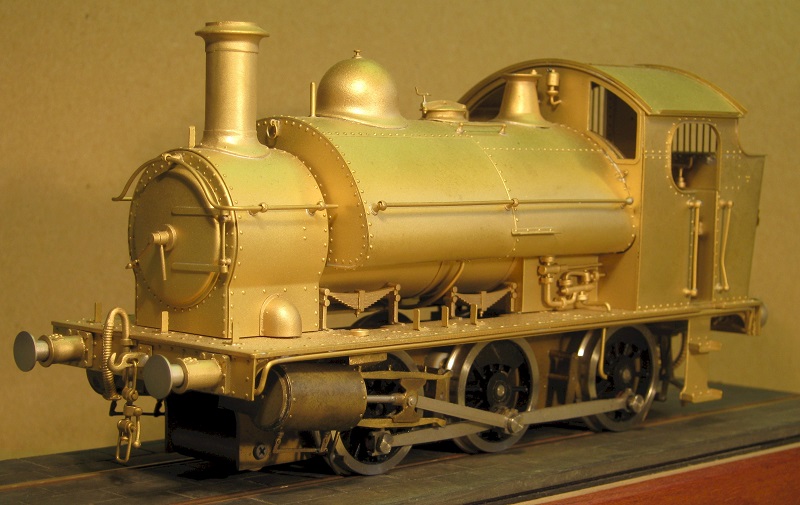
The Tower Brass model of GWR 1361 Class as received
Like so many of the models from this stable, particularly the earlier ones, the upper works are well engineered and are quite well detailed compared to the lower works, which rather let the models down, but they do all run very well. On this model, I have undertaken my usual reworkings of the motion, draw gear, vacuum and steam heat pipes and so on but the frames required quite drastic surgery to set them at more nearly the correct distance apart and to spring the driven centre axle, which was rigid in the frames.
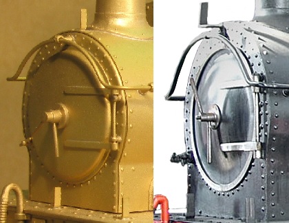
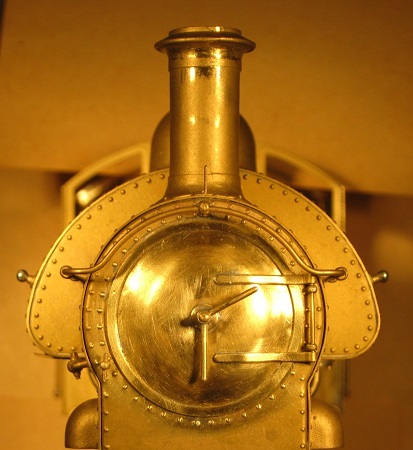
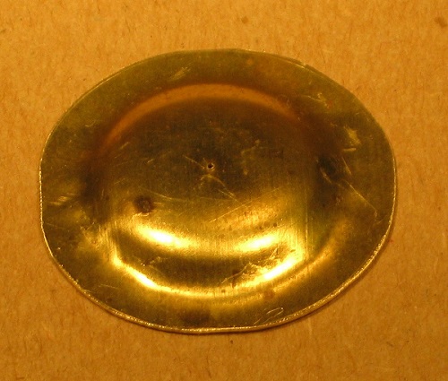
| Unfortunately, the smokebox door on the Tower Brass 1361 Class model is quite wrong but, being part of the ‘face’ of the locomotive, it really does need to be rather better so I made a new one. |
The smokebox door on the model (left) and on the prototype (right) |
There are suitable castings available but I decided to make a pressing. I have
done this before, but not for a door with a dished reverse curve such as this
one, so it seemed like an interesting challenge. The principle is to make a
punch and die with a means of restraining within it a disc of brass which is to
be formed into the required shape.
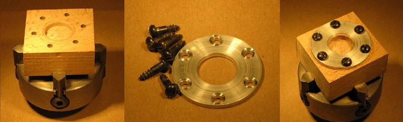
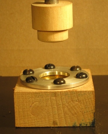
The wooden die (left) and the restrainer (centre) assembled (right)
| I machined a hole in a piece of hardwood to form the die and I turned an
aluminium ring as the restrainer, which is held to the wooden die with six
roundhead screws.
I turned the head of the punch from a piece of dowel and mounted it on a steel shaft. The roughly sawn out brass disc (the blank) is firmly trapped between the restrainer and the die and the punch is pressed through the restrainer to form the blank into a dished door. Properly, the punch and die should be mounted in a press but I used my larger pillar drill. |
Punch and die lined up in the pillar drill |
 The first attempt at a pressing |
For my first attempt (left), I used a brass blank of 15 thou (0.38mm) thickness and it was a reasonable success, but for the coggles in two places around the edge. My second attempt with a blank of 10 thou (0.25mm) thickness was as near perfect as things get in this less-than-perfect world, so I was well pleased. |
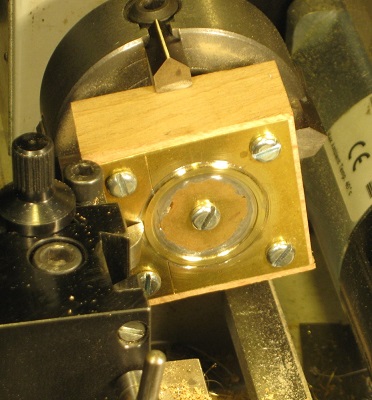
| The second task was to make the thin surrounding ring. The challenge in many machining operations is getting a good hold of the job. In this case, the simplest way that I knew of was to use a ‘solder chuck’: simply put, you solder the job to something that you can get a good hold of, machine the job and then unsolder it again. I soldered a ring, which I had roughly sawn out of 15 thou thick brass, to a piece of waste etch of the same thickness and screwed this to a piece of hardwood (the back of the piece that I had used earlier as the die) that I could easily hold in a four-jaw chuck. In the image (right), the inside diameter of the ring has been bored and the outside diameter is now being turned to size. |
Machining the surrounding ring
|
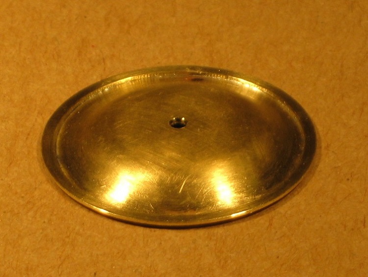
The finished door
|
The new door in place |
There is a sizable hole in the front of the smokebox into which the
dished part of the finished door (above) nicely fits so that the ring
sits down flush on the front, centred on the surrounding rivets. To complete the job, I reattached the hinges and made up a new set of dart handles. I modified the hinges slightly to look more like the prototype but, in the end, I decided against trying to move the lower hinge pin, which should be below the lower hinge, as there was really insufficient room for it in the correct place. This is one of the limitations of working with RTR models and kits, even very good ones; there are some design errors that require so much work to correct that it’s just not worth the effort, otherwise I would be better placed working from scratch. |
For comparison, here is the replacement door in comparison to the original:
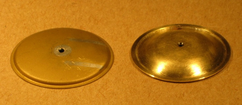
Original door (left) and its replacement
And here is what the finished front end now looks like in comparison to how it looked before:
![7mm scale [0 gauge] Smokebox - GWR 1361 Class](images/RailwayModels/GWR1361SmokeboxB_A.jpg)
Before (left) and after
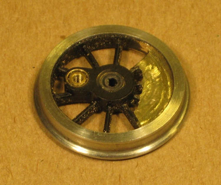
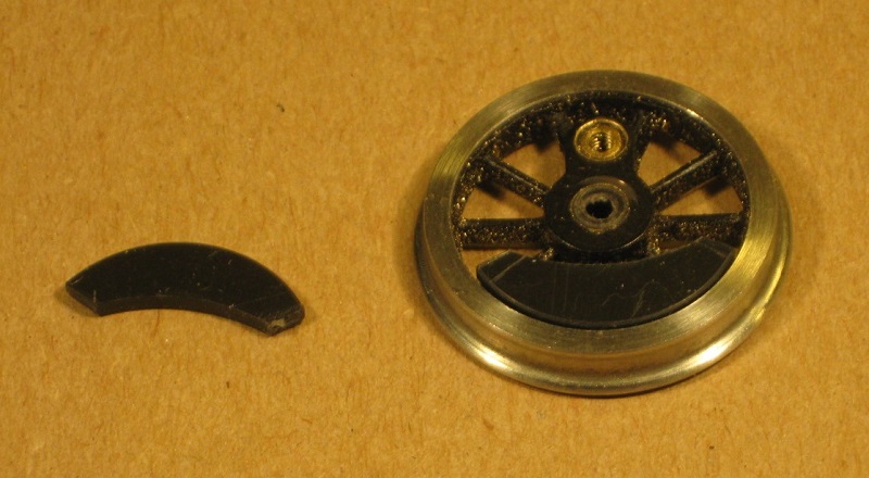
| On the model as supplied, the balance weights were the correct shape but their
front faces were barely flush with the rim of the wheel whereas they should
stand slightly proud of the tyre. The first job was to mill away the front of the old balance weights (right) to make a suitable base onto which I could epoxy glue some new styrene balance weights. |
 |
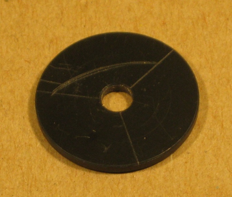 |
I have made balance weights before, both from brass and from styrene, by turning discs and then marking out to cut the inner arc, but I have never found the latter that easy. |
| This time, I turned out two blank discs and, although I started the marking out, I decided to machine the inner arcs on each of the sectors. |
 |
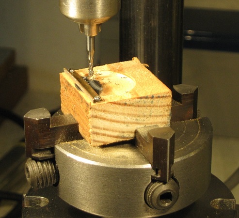 |
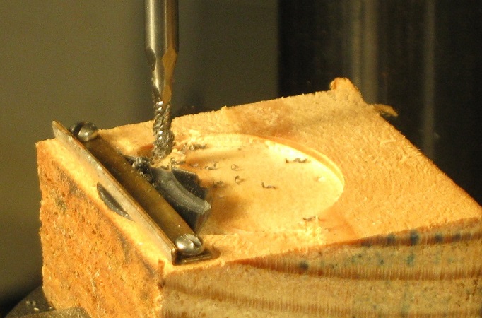
I machined a shallow hole in piece of softwood that was of the same diameter as the blank discs and I then screwed a little bridge across it to hold the embryo balance weight whilst I machined the inner arc. |
| Clearly, the inner arc is of a greater diameter than the blank disc
so it was necessary to offset the piece of soft wood in the chuck by the
requisite amount. I mounted the chuck on a rotary table, which I
then moved to the appropriate position so that the finished balance
weight was the correct width. Milling the styrene was easy and was a simple matter of rotating the rotary table a few times until the waste material fell away. |
 |
 |
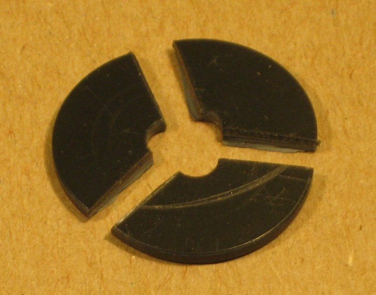
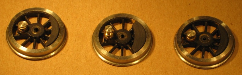
The raw balance weights were over length but I used epoxy to glue them in position and then I trimmed them to length in line with a spoke. |
Finally, I machined some new crankpins and bushes to suit the modified rods.
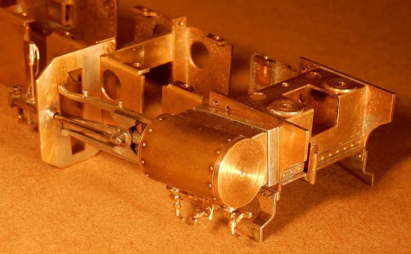
| Along with other smaller alterations and improvements, I reworked the
cylinders. The cylinders on the model appeared rather weedy in comparison to
those on the drawing and in photographs, which are rather beefy for such a small
loco.
I machined a spool-like core with cylinder covers at each end, around which I was able to wrap the original cladding. I was also able to reuse the stuffing box and the slidebars from the original arrangements. Although I had increased the width of the frames (see below), I had to make up a thin spacer to push out the cylinders to their correct overall spacing. |
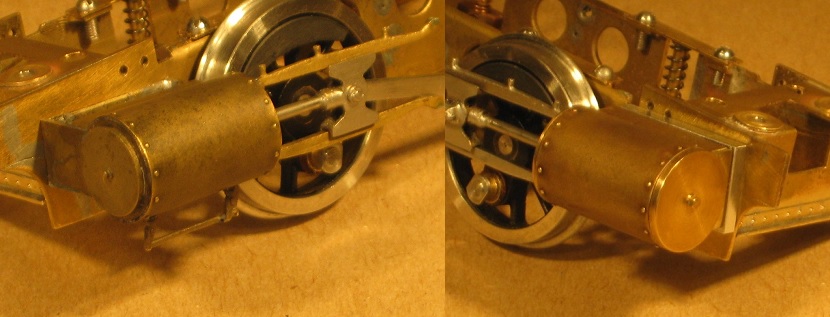 Cylinder before (left) and after reworking |
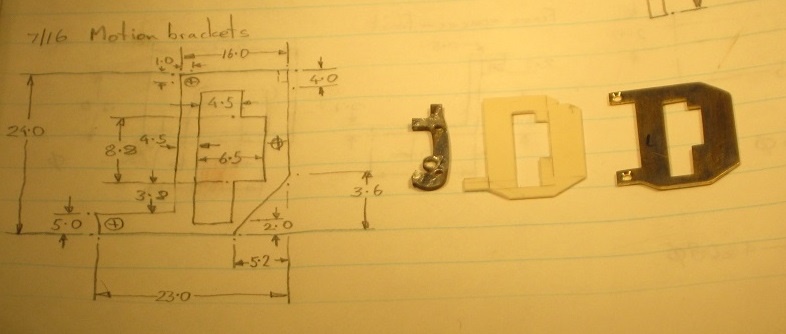 Motion bracket: dimensioned sketch (left), original, trial pattern, replacement |
The original motion brackets were a quite unlike the massive
brackets of the prototype so I drew up a dimensioned sketch and made a
trial pattern in plastic before making the two parts in brass. As may be seen in the image (left), I modified the design to include an additional fixing lug at the top of the bracket. |
| The right hand motion bracket is in place (right) and, just in board of it, may be seen the bracket to support the leading brake hanger. The vacuum ejector pump, which is mounted on the motion bracket and driven from the right hand crosshead, was not in line with the piston rod as it should have been so I corrected this and added more detail. |
 |
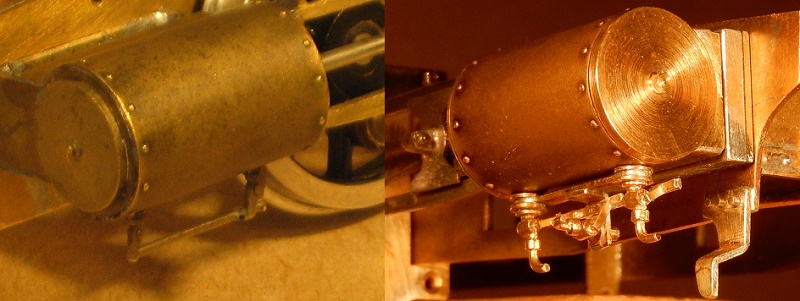 |
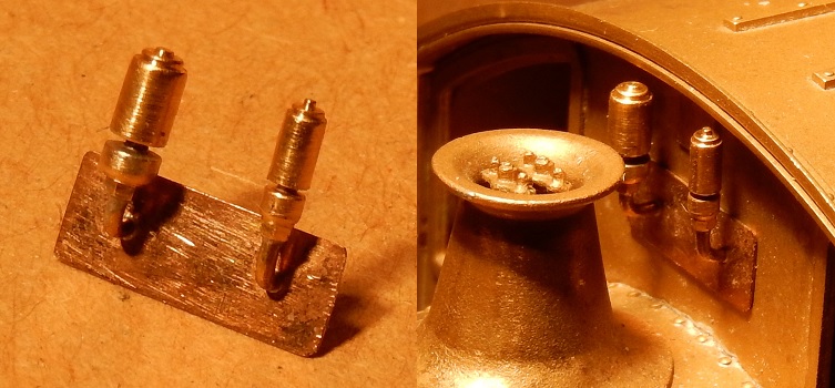
The cylinder drain cocks that were originally fitted to the model were of a later pattern (far left) so I made up assemblies to represent the earlier pattern (that have been reinstated on preserved No. 1363) using some castings from Warren Shephard as a basis (right and below). |
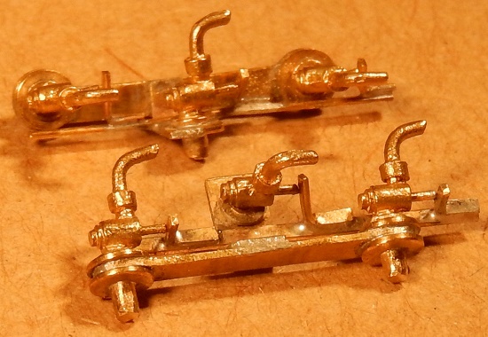
Cylinder drain cock assemblies
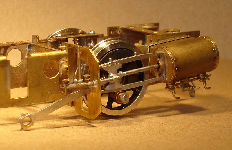
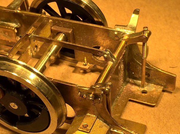
| The motor and gearbox were originally rigidly attached to the frames
so that, although the leading and trailing axles were sprung (with
Tufnol hornblocks in guides with springs and keeper plates from above),
the centre axle was fixed. I machined up an additional pair of Tufnol hornblocks for the centre axle and arranged to spring them and to retain them with keeper plates in a similar fashion. I discarded the motor mounting plate so the motor and gearbox are now free to float with the centre axle. |
 |
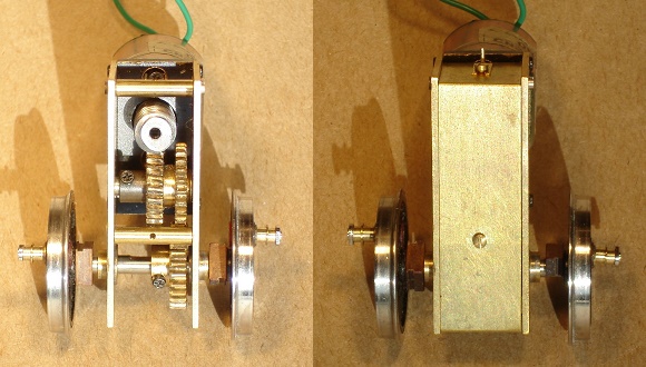 |
I always enclose the gearboxes on my locomotives; this was important when they normally ran on a friend’s extensive garden railway but it seems to be good practice to me anyway. I covered the unguarded gears (far left) with a simple cover plate that is screwed to two of the gearbox stretchers and sits between the cheeks. The upper screw also retains a bracket to hold a pin that engages on a stretcher in the frames to provide the resisting torque for the motor (ie it prevents the motor from rocking backwards and forwards within the body but it does not impeded its rise and fall with the axle). |
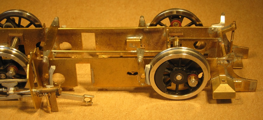
| I reduced the depth of the frames, as they were far too deep, and I
exchanged them left for right, which allowed me to push the frames out
so that they were 27.5mm overall and to fit wider stretches (frame
spacers). The flanges at the top of the frames, which originally turned
outwards, now turned inwards and I removed all the portions that were
not required to leave lugs to hold the horn block keepers and springs;
not only did this improve the appearance, it allowed the motor and
gearbox to fit easily between the frames. Although I needed to allow for this extra width in reattaching the cylinders, sand boxes and so on, it was not difficult and resulted in a pleasingly small gap between the back of the wheel and the frames. |
 |
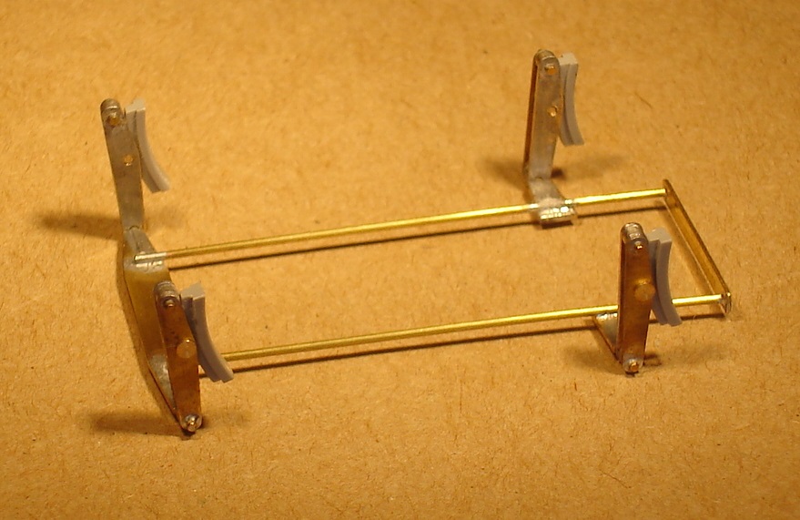 |
Surprisingly perhaps, the GWR 1361 class has no brakes on it leading
wheels so I needed only machine four plastic brake blocks and four pairs
of brake hangers, and to fabricate the associated rod and plate work.
|
|
The assembly neatly clips over the four brackets on
the frames to butt up against the remainder of the brake rods and the
cross-shaft. Also visible in this image are the representations
that I made of the firebox washout plugs that are visible between the
frames, in front of the trailing brake shoe.
|
 |
 |
With more authentic shallower frames, I was able to make up decent looking brackets for the cross-shaft and to make suitable cranks for the hand and steam brake operating gear. |
| On the body, other than the smokebox door, I reckoned that there was relatively little work to do. There was nothing very wrong with the original cast whistles but I knew that I could easily make better looking turnings. |
 |
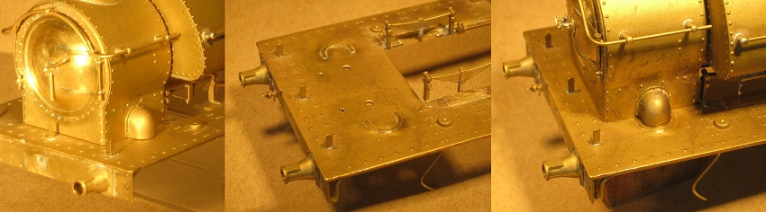 |
Whereas the covers to the steam pipes had flanges at the smokebox, there were none at the running plate (far left) so, using a coping saw, I cut out some horseshoe-shaped flanges and soldered them on (centre and right). |
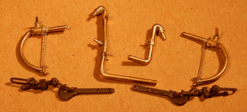
| As usual with these RTR models manufactured by San Cheng Crafts, I reworked the drawgear, vacuum and steam heat pipes/hoses. Although I have described this before in reworking an LMS 8F, Jubilee and Black Five, for example, here is the result for this loco. To provide a good key and to help hide any chips, I have chemically blackened the drawgear prior to painting. |
 |
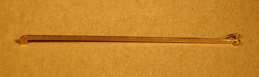 |
The representation of the reach rod and crank was a rather caricature of an affair but I improved the reach rod with a yoke at the outer end; the inner end (to the left) disappears inside the cab, so it needed no alteration. |